|
|
Information box |
The main purpose of this site is to extend the
intraoperative monitoring of the pelvic organs as part of the
general nervous system to include the neurophysiologic
parameters with intraoperative navigation guided with Skyra 3
tesla MRI and other radiologic facilities to merge the
morphologic and histochemical data in concordance with the
functional data, trying during that to include the laparoscopic
surgeries with merging LION procedures in patients with spinal
cord injuries.
 CNS Clinic
Located in Jordan Amman near Al-Shmaisani hospital, where all
ambulatory activity is going on.
Contact: Tel: +96265677695, +96265677694.
Skyra running
A magnetom Skyra 3 tesla MRI with all clinical applications
started to run in our hospital in 28-October-2013.
Shmaisani hospital
The hospital where the project is located and running diagnostic
and surgical activity. |
|
 |
|
|
 |
Basic
Principles of magnetism |
 |
The nuclei of
many kinds of atoms, commonly hydrogen, are tiny
magnets. In the earth’s magnetic field they line
up to some extent just as you walk around. When
you walk past a piece of iron they’ll flop
around in different directions. Think of us as
having microscopic compass needles precessing
(spinning on their axes like gyroscopes) in an
orderly direction. To make an MR image, this
tendency of the nuclei to line up in the
direction of a magnetic field can be manipulated
and measured. Since the nuclei from different
regions of the body can be made to precess at
different frequencies (their magneto-resonance
frequencies), the electromagnetic energy at
these frequencies yields signals that are
location dependent. Computer images can be
calculated, enhanced, and displayed. MRI is safe
because only a very tiny amount of energy is
absorbed or emitted, corresponding to the amount
of energy in radio waves, to which we are
constantly exposed. MRI does not affect any
chemical processes. It doesn’t change molecules
at all. The atomic nuclei within the molecules
just report what is happening.
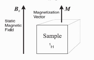
In the presence of a static magnetic field (B0),
the atomic nuclei possess energy which differs
depending on their orientation( ΔE). ΔE
determines the strength of the signal and is
related to the resonance frequencies (ν), by
Planck’s constant (h).
(Planck's constant h = 6.626x10⁻³⁴
J.s ).
ΔE = hv
(1)
The size of ΔE and v depend on the
size of the static magnetic field, (B0), and
the magnetogyric ratio, (ϒ),
a characteristic of each kind of atomic nucleus, as shown in
equation 2. This is the Larmor (Joseph Larmor, 1857 - 1942)
relationship. The Larmor equation
(2) is fundamental to all of nuclear magnetic resonance (NMR)
and its subfield, MRI.
v = (ϒ/2π )B0
(2) ( Larmor equation: Frequency rate of precession is
proportional to the strength of magnetic field -
ಎ= ϒ*
B )
Together these two equations determine that
ΔE = hv = h (ϒ/2π
)B0
(3) ( This equation means that, the more the strength of
the magnet, the higher the RF and the better the contrast and
the resolution of the MRI data).
 |
Basic
Principles of MRI |
 |
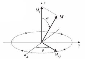
The hydrogen (1^H) atom inside
body possess “spin”
• In the absence of external magnetic field, the
spin directions of all atoms are random and
cancel each other.
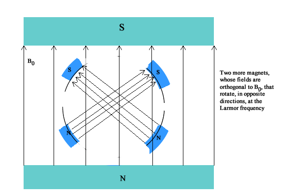
• When placed in an external magnetic field, the
spins align with the external field.
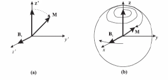
• By applying an rotating magnetic field in the
direction orthogonal to the static field, the
spins can be pulled away from the z-axis with an
angle \alpha
• The bulk magnetization vector rotates around z
at the Larmor frequency (precess)
• The precession relaxes gradually, with the
xy-component reduces in time, z-component
increases
• The xy component of the magnetization vector
produces a voltage signal, which is the NMR
signal we measure
|
|
What is spin? |
|
• Spin is a fundamental
property of nature like electrical charge or
mass. Spin comes in multiples of 1/2 and can be
+ or -. Protons, electrons, and neutrons possess
spin. Individual unpaired electrons, protons,
and neutrons each possesses a spin of ½ or - ½.
• Two or more particles with spins having
opposite signs can pair up to eliminate the
observable manifestations of spin.
• In nuclear magnetic resonance, it is unpaired
nuclear spins that are of importance.
|
|
Nuclear Spin |
|
• A nucleus consists of protons and
neutrons
• When the total number of protons and
neutrons (=mass number A) is odd or the
total number of protons is odd, a
nucleus has an angular momentum (\phi)
and hence spin – Ex. Hydrogen (1^H) (1
proton), 13^C
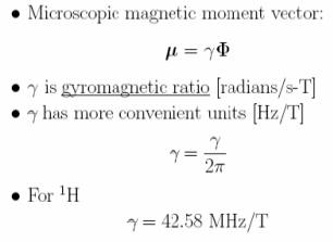
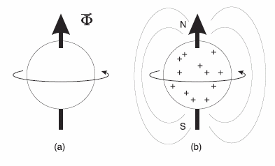
• The spin of a nucleus generates a
magnetic filed, which has a magnetic
moment (\mu)
• The spin causes the nucleus behave
like a tiny magnet with a north and
south pole
 Angular momentum vs magnetic moment
 |
 |
| |
|
|
|
Nuclear spin
system |
|
• Collection of identical nuclei in a given
sample of material (also known as spin packet, a
voxel in the imaged volume)
• In the absence of external magnetic field, the
spin orientations of the nuclei are random and
cancel each other
• When placed in a magnetic field, the
microscopic spins tend to align with the
external field, producing a net bulk
magnetization aligned with the external field.
|
|
Nuclear
Magnetization |
|
• Put sample in external magnetic field: B0=B0ž
• Spins align in one of two directions:
-540 of ž
"up" (Low energy state)
-180-540 off ž
"down" (high energy state)
• Slight preference for "up" direction: N-/N+ =
e-E/kT
• Sample becomes magnetized.
• Magnetization vector:

|
|
Precession |
|
• Put patient in a static field B_0 (much stronger than the
earth’s field)
• (step 1) Wait until the nuclear magnetization reaches an
equilibrium (align with B_0)
• Applying a rotating magnetic field B_1 (much weaker than B_0)
to bring M to an initial angle \alpha with B_0 (rotating
freq=Larmor freq.)
• M(t) precess around B_0 at Larmor frequency around B_0 axis (z
direction) with angle \alpha
• The component in z increases in time (longitudinal relaxation)
with time constant T1
• The component in x-y plane reduces in time (transverse
relaxation) with time constant T2
• Measure the transverse component at a certain time after the
excitation (NMR signal)
• Go back to step 1
• By using different excitation pulse sequences, the signal
amplitude can reflect mainly the proton density, T1 or T2 at a
given voxel
|
|
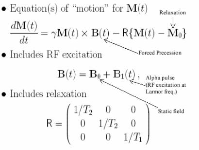
Evolution of magnetization when a time
varying magnetic field is applied |
|
- M=M(x,t)
- Relation to bulk angular momentum J : M=
 J J
- Focus on small sample
→ voxel
- M=M(t)
- Equations of motion = Bloch equations
- M(t) experiences a torque when an
external magnetic field B(t) is applied
torque is
 = MxB
= MxB
- Torque is related to angular momentum
=dJ/dt
- Eliminate J to yield
dM(t)/dt =
M(t) x B(t)
- Valid for "short" times
Using the right hand rule, M will rotate
around z if M is not aligned with z
| |
i
j k |
|
| MxB = |
Mx My
Mz |
|
| |
Bx By
Bz |
|
| |
= (MyBz-MzBy
) i + (MzBx-MxBz
) j+ ( MxBy-MyBx
)k |
|
Direction of MxB follows “right hand” rule
|
|
Solution under
a Static Field with an Initial Angle |
|
• B(t)=[0,0,B_0]
• MxB = M_y B_0 i - M_x B_0 j + 0 k
• dM_x/dt = M_y B_0
• dM_y/dt = - M_x B_0
|
|
Precession Due to a Static Field with an
Initial Angle |
|
|
|
Longitudinal
and Transverse Components |
|
M(t) = (Mx(t),
My(t), Mz(t))
Think of M(t) with two components:
Longitudinal magnetization - Mz(t) - No
change
Transverse magnetization - Mxy(t) =
Mx(t) + jMy(t)
- Rapidly rotating
|
|
NMR Signal |
|
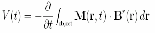
• The rapidly rotating transverse
magnetization (M_xy) creates a radio frequency excitation within
the sample.
• If we put a coil of wire outside the sample, the RF excitation
will induce a voltage signal.
• In MRI, we measure this voltage signal.
• Voltage produced is (Faraday’s Law of Induction) |
 |
| |
Br(r) is field produced at r by unit
direct current in coil around sample. |
|
|
Source of MR
Contrast |
|
• Different tissues vary in T1, T2 and PD (proton density)
• The pulse sequence parameters can be designed so that the
captured signal magnitude is mainly influenced by one of these
parameters
• Pulse sequence parameters
– Tip angle \alpha
– Echo time TE
– Pulse repetition time TR
|
|
Simplification |
|
- B^r(r)=B^r
- Longitudinal magnetization changes too slow
- Transverse magnetization dominates
- Final expression:

|V| = ಎ0VsM0
sin ∝Br
Recall ಎ0 =
ϒB0, Mo
= ( B0 ϒ2h2
/4kT ). PD
Therefore |V|
∝
B02,
PD
|
|
How to tilt M to an initial angle? |
|
• Applying a circularly polarized
(rotating) magnetic field B_1(t) in the x-y plane with
the same Larmor frequency forces the magnetization
vector to tilt down to the x-y plane
– B_1(t) has two orthogonal components, in x and y
directions respectively, and is produced by using
quadrature RF coil
– Simplest envelop B_1,e is a rectangular pulse
• Motion of M(t) is spiral |
 |
| |
|
|
|
Circulatory
Polarized Magnetic Field |
|
|
|
Tip Angle |
|
• If M is parallel to z-axis before the RF excitation pulse,
the tip angle
after the excitation (with duration \tau_p) is:
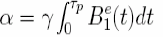
• If B_1^e(t) is rectangular
∝ =
ϒB1p
• Pulse that leads to \alpha=\pi/2 is called “\pi over 2 pulse”,
which
elicits the largest transverse component M_xy, and hence largest
NMR signal
• Pulse that leads to \alpha=\pi is called “\pi pulse” or
inverse pulse,
which is used to induce spin echo (later)
• The excitation pulse (envelop of B_1(t)) is also called “an
alpha
pulse”
|
|
Relaxation |
|
- Magnetization cannot precess forever
- Two independent relaxation processes
- Transverse relaxation -
≡spin-spin
relaxation
- Longitudinal relaxation -
≡spin-lattice
relaxation
- Detailed prosperities differ in tissues
- Gives rise to tissue contrast.
|
|
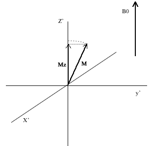
Longitudinal
Relaxation |
|
• The magnetization vectors tend to return to
equilibrium
state (parallel to B_0) |
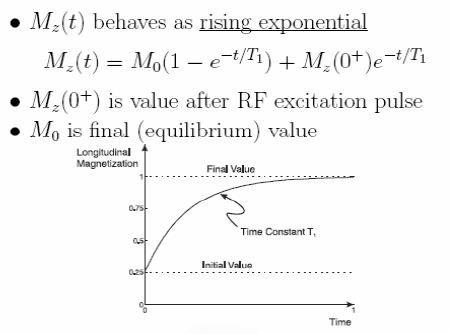 |
= M_0 cos\alpha = 0 for \pi/2 pulse |
In the laboratory frame, M takes a
spiraling path back to its equilibrium orientation. But
here in the rotating frame, it simply rotates in the y
׳-z ׳ plane. The z component of M, Mz, grows back into
its equilibrium value, exponentially: Mz =
|M|(1 - e-t/T1) |
| |
|
|
|
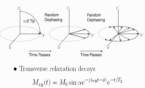
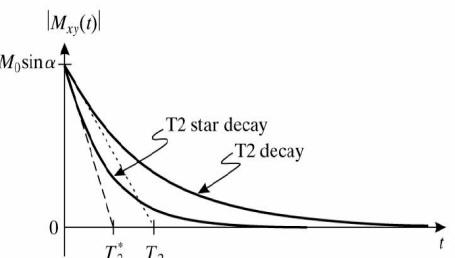
Transverse
Relaxation |
|
| |
|
• The strength of the magnetic field in the
immediate environment of a
1H nucleus is not homogeneous due to presence of other
nucleus
(and their interactions)
• Hence the Larmor frequencies of nearby nuclides are
slightly different
(some spins faster, some slower)
– Spin-spin interactions
• This causes dephasing of the xy components of the
magnetization
vectors, leading to exponential decay of M_• T_2 is
called transverse relaxation time, which is the time for
M_xy
to decrease by 1/e.
• Also called spin-spin relaxation time
• T2 is much smaller than T1
– For tissue in body, T2: 25-250ms, T1: 250-2500 ms |
 |
|
|
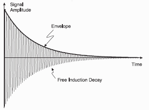
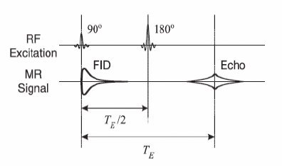
Free Induction Decay |
|
• The voltage signal (NMR signal) produced by
decaying M_xy also
decays
• This is called free induction decay (FID), and is the
signal we measure
in MRI |
 |
| |
|
|
|
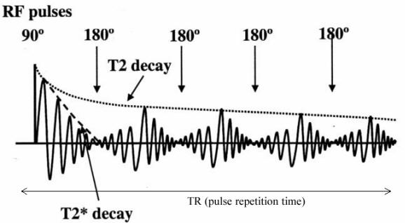
T2 Star Decay |
|
• Received signal actually decays faster than
T_2 (having a shorter relaxation
time T_2^*)
• Caused by fixed spatial variation of the static field B_0 due
to imperfection
of the magnet
– Accelerates the dephasing of magnetization vectors
– Note that T2 is caused by spatial variation of the static
field due to interactions of
nearby spins
• The initial decay rate is governed by T_2^* , but the later
decay by T_2. |
 |
| |
|
|
|
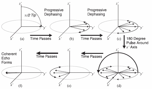
Formation of spin echo |
|
• By applying a 180 degree pulse, the
dephased spins can recover their coherence, and
form an echo signal
|
|
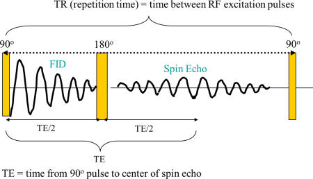
RF Pulse
Sequence and Corresponding NMR Signal |
|
|
|
Spin echo sequence |
|
• Multiple π pulses create “Carr-Purcell-Meiboom-Gill (CPMG)”
sequence
• Echo Magnitude Decays with time constant T2
|
|
Bloch
Equations |
|
|
|
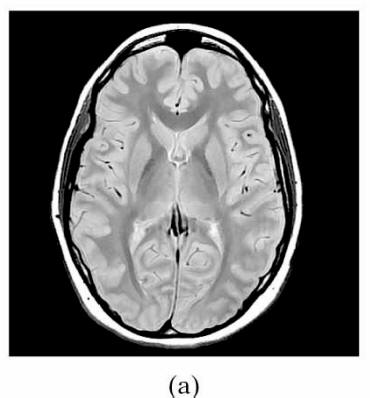
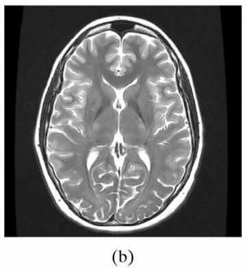
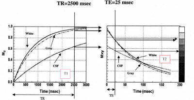
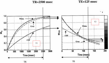
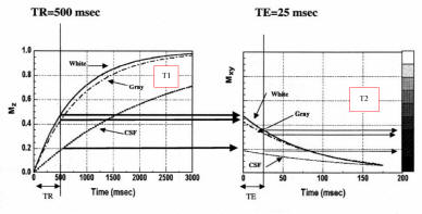
Typical Brain Tissue Parameters |
|
| |
Proton Density |
T2 (ms) |
T1 (ms) |
| White matter |
0.61 |
67 |
510 |
| Gray matter |
0.69 |
77 |
760 |
| CSF |
1.00 |
280 |
2650 |
| |
 |
 |
|
|
|
Weighting |
TR |
TE |
|
T1 |
Short |
Short |
|
T2
|
Long |
Long |
|
PD |
Long |
Short |
|
| |
• Signal at equilibrium proportional to
PD

• Long TR:
– Minimizes effects of different degrees of saturation
(T1 contrast)
– Maximizes signal (all return to equilibrium)
• Short TE:
– Minimizes T2 contrast
– Maximizes signal |
• Long TR:
– Minimizes influence of different T1
• Long TE:
– Maximizes T2 contrast
– Relatively poor SNR |
• Short TR:
– Maximizes T1 contrast due to different degrees of
saturation
– If TR too long, tissues with different T1 all return
equilibrium already
• Short TE:
– Minimizes T2 influence, maximizes signal |
| |
 |
 |
 |
|
|
Summary:
Process Involved in MRI |
|
• Put patient in a static field B_0 in z-direction
• (step 1) Wait until the bulk magnetization reaches an
equilibrium (align with B_0)
• Apply a rotating field (alpha pulse) in the xy plane to bring
M to an initial angle \alpha with B_0. Typically \alpha=\pi/2
• M(t) precesses around B_0 (z direction) at Larmor freq. with
angle \alpha
• The component in z increases in time (longitudinal relaxation)
with time constant T1
• The component in x-y plane reduces in time (transverse
relaxation) with time constant T2
• Apply \pi pulse to induce echo to bring transverse components
in phase to increase signal strength
• Measure the transverse component at different times (NMR
signal), to deduce T1 or T2
• Go back to step 1
• By using different excitation pulse sequences (differing in
TE, TR, \alpha), the signal amplitude can reflect mainly the
proton density, T1 or T2 at a given voxel
|
|
Transforming the acquired MRI data to images |
|
 |
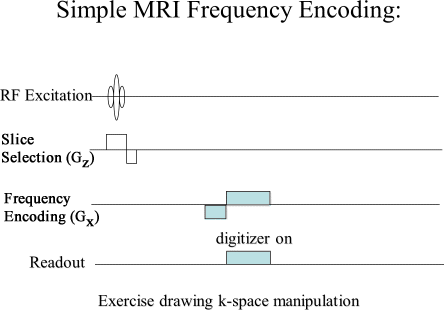 |
MRI task is to acquire k-space image then transform
to a spatial-domain image. kx is sampled (read out) in
real time to give N samples.
ky is adjusted before each readout. MRI image is the
magnitude of the Fourier transform of the k-space image. |
|
 |
 |
| |
|
|
|
Gradient Echo
Imaging |
|
|
•Signal
is generated by magnetic field refocusing mechanism
only (the use of negative and positive gradient)
•Signal
intensity is governed by
S = So
e-TE/T2*
•Can
be used to measure T2* value of the tissue
•R2*
= R2 + R2ih
+R2ph
(R2=1/T2)
•Used
in 3D and BOLD fMRI
|
 |
| |
|
|
|
Annotations |
|
- The Larmor frequency
f0 ( Center frequency is the frequency rate at which protons
spin (precess) with just static magnetic field) for a 1.5 T magnet is 1.5(T)*42.56(MHz T-1) = 63.8 MHz, for
3T= 128 MHz, for 7T = 300 MHz and for 11.7T = 500 MHz. The
gyromagnetic ratio here is for 1H
- One gauss is defined as one maxwell per
square centimeter; it equals 1×10⁻⁴ tesla.
- Typical values
10−9–10−8 gauss: the human brain
magnetic field
0.31–0.58 gauss: the Earth's magnetic field on its surface
25 gauss: the Earth's magnetic field in its core
50 gauss: a typical refrigerator magnet
100 gauss: a small iron magnet
2000 gauss: a small neodymium-iron-boron (NIB) magnet
15,000-30,000 gauss: a medical magnetic resonance imaging
electromagnet
1012–1013 gauss: the surface of a
neutron star
4×10¹³ gauss: the quantum electrodynamic
threshold
1015 gauss: the magnetic field of some newly
created magnetars
1017 gauss: the upper limit to neutron star
magnetism, no known object in the universe can generate a
stronger magnetic field
- The relation between FOV and gradient direction: FOV is
defined as bandwidth divided by the gradient times and
gyromagnetic ration
- Bandwidth is defined as follows: BW = 1/
ΔT,
- Δk = 1/FOV where
k is the spatial frequency of k-space and
Δk are cycles per distance
The gyromagnetic
ratio is dependent upon the atoms:
|
Nucleus |
γ
/ 106 rad s−1 T−1 |
γ/2π
/ MHz T−1 |
|
1H |
267.513 |
42.576 |
|
2H |
41.065 |
6.536 |
|
3He |
-203.789 |
-32.434 |
|
7Li |
103.962 |
16.546 |
|
13C |
67.262 |
10.705 |
|
14N |
19.331 |
3.077 |
|
15N |
-27.116 |
-4.316 |
|
17O |
-36.264 |
-5.772 |
|
19F |
251.662 |
40.053 |
|
23Na |
70.761 |
11.262 |
|
31P |
108.291 |
17.235 |
|
129Xe |
-73.997 |
-11.777 |
|
|
|


 Equilibrium
value: M0 : same direction as B0 and
depends on x=(x,y,z) only. Magnitude: M0
Equilibrium
value: M0 : same direction as B0 and
depends on x=(x,y,z) only. Magnitude: M0