|
|
Information box |
The main purpose of this site is to extend the
intraoperative monitoring of the pelvic organs as part of the
general nervous system to include the neurophysiologic
parameters with intraoperative navigation guided with Skyra 3
tesla MRI and other radiologic facilities to merge the
morphologic and histochemical data in concordance with the
functional data, trying during that to include the laparoscopic
surgeries with merging LION procedures in patients with spinal
cord injuries.
 CNS Clinic
Located in Jordan Amman near Al-Shmaisani hospital, where all
ambulatory activity is going on.
Contact: Tel: +96265677695, +96265677694.
Skyra running
A magnetom Skyra 3 tesla MRI with all clinical applications
started to run in our hospital in 28-October-2013.
Shmaisani hospital
The hospital where the project is located and running diagnostic
and surgical activity. |
|
 |
|
|
Spin Echo family of sequences:
- Spin Echo (SE) - Single, Double, and Multi Echo (up to 32
echoes); Inversion Recovery (IR)
- 2D / 3D Turbo Spin Echo (TSE) - Restore technique for shorter
TR times while maintaining excellent T2 contrast; TurboIR:
Inversion Recovery for STIR, DarkFluid T1 and T2, TrueIR; Echo
Sharing for dual-contrast TSE
- 2D / 3D HASTE (Half-Fourier Acquisition with Single Shot Turbo
Spin Echo) - Inversion Recovery for STIR and DarkFluid contrast
- SPACE for 3D imaging with high isotropic resolution with T1,
T2, PD, and DarkFluid Contrast
Gradient Echo family of sequences:
- 2D / 3D FLASH (spoiled GRE) - dual echo for in- / opposed
phase imaging 3D VIBE (Volume Interpolated Breathhold
Examination) - quick fat saturation; double echo for in-phase /
opposed phase 3D imaging; DynaVIBE: Inline 3D elastic motion
correction for multi phase data sets of the abdomen; Inline
Breast Evaluation
- 2D / 3D MEDIC (Multi Echo Data Image Combination) for high
resolution T2 weighted orthopedic imaging and excellent contrast
- 2D / 3D TurboFLASH - 3D MPRAGE; single shot T1 weighted
imaging e.g. for abdominal imaging during free breathing
- 3D GRE for field mapping
- 2D / 3D FISP (Fast Imaging with Steady State Precession)
- 2D / 3D PSIF - PSIF Diffusion
- Echo Planar Imaging (EPI) - diffusion-weighted; single shot SE
and FID e.g. for BOLD imaging and Perfusion-weighted imaging; 2D
/ 3D Segmented EPI (SE and FID)
- ce-MRA sequence with Inline subtraction and Inline MIP
- 2D / 3D Time-of-Flight (ToF) Angiography - single slab and
multi slab; triggered and segmented
- 2D / 3D Phase Contrast Angiography •
- syngo BEAT Tool - TrueFISP segmented; 2D FLASH segmented;
- Magnetization-prepared TrueFISP (IR, SR, FS); IR TI scout;
Retrogating
 |
Pulse Sequence |
 |
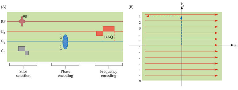
A pulse sequence is a preselected set of defined RF and gradient
pulses, usually repeated many times during a scan, wherein the
time interval between pulses and the amplitude and shape of the
gradient waveforms will control NMR signal reception and affect
the characteristics of the MR images. Pulse sequences are
computer programs that control all hardware aspects of the MRI
measurement process.
Usual to describe pulse sequences, is to list the repetition
time (TR), the echo time (TE), if using inversion recovery, the
inversion time (TI) with all times given in milliseconds, and in
case of a gradient echo sequence, the flip angle. For example,
3000/30/1000 would indicate an inversion recovery pulse sequence
with TR of 3000 msec., TE of 30 msec., and TI of 1000 msec.
Specific pulse sequence weightings are dependent on the field
strength, the manufacturer and the pathology.
 |
Basic Pulse
Sequence Diagram |
 |
 |
|
| |
|
 Spin Echo Sequence
1. Dual Echo Sequence
2. Modified Spin Echo
3. Multi Echo Multiplanar
4. Partial Saturation Spin Echo
5. Variable Echo Multiplanar
Fast Spin Echo
1. Carr Purcell Sequence
2. Carr Purcell Meiboom Gill Sequence
3. Double Fast Spin Echo
4. Double Turbo Spin Echo
5. Dual Echo Fast Acquisition Interleaved Spin Echo
6. Half Fourier Acquisition Single Shot Turbo Spin Echo
7. Multiple Echo Single Shot
8. Rapid Acquisition with Refocused Echoes
9. Turbo Spin Echo
10.Ultrashort Turbo Spin Echo
Inversion Recovery
Sequence
1. Flow Sensitive Alternating Inversion Recovery
2. Fluid Attenuation Inversion Recovery
3. Inversion Recovery Spin Echo
4. Short T1 Inversion Recovery
5. Turbo Inversion Recovery
|
|
Spin Echo
Sequence |
|
|
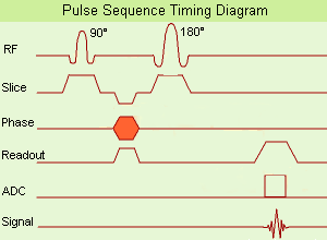
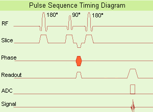
(SE) The most common pulse
sequence used in MR imaging is based of the
detection of a spin or Hahn echo. It uses 90°
radio frequency pulses to excite the
magnetization and one or more 180° pulses to
refocus the spins to generate signal echoes
named spin echoes (SE).
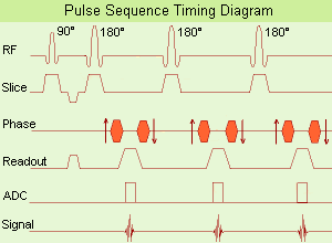
In the pulse sequence timing diagram, the
simplest form of a spin echo sequence is
illustrated.
The 90° excitation pulse rotates the
longitudinal magnetization (Mz) into the
xy-plane and the dephasing of the transverse
magnetization (Mxy) starts.
The following application of a 180° refocusing
pulse (rotates the magnetization in the x-plane)
generates signal echoes. The purpose of the 180°
pulse is to rephase the spins, causing them to
regain coherence and thereby to recover
transverse magnetization, producing a spin echo.
The recovery of the z-magnetization occurs with
the T1 relaxation time and typically at a much
slower rate than the T2-decay, because in
general T1 is greater than T2 for living tissues
and is in the range of 100–2000 ms.
The SE pulse sequence was devised in the early
days of NMR days by Carr and Purcell and exists
now in many forms: the multi echo pulse sequence
using single or multislice acquisition, the fast
spin echo (FSE/TSE) pulse sequence, echo planar
imaging (EPI) pulse sequence and the gradient
and spin echo (GRASE) pulse sequence;; all are
basically spin echo sequences.
In the simplest form of SE imaging, the pulse
sequence has to be repeated as many times as the
image has lines.
Contrast values:
PD weighted: Short TE (20 ms) and long TR.
T1 weighted: Short TE (10-20 ms) and short TR
(300-600 ms)
T2 weighted: Long TE (greater than 60 ms) and
long TR (greater than 1600 ms)
With spin echo imaging no T2* occurs, caused by
the 180° refocusing pulse. For this reason, spin
echo sequences are more robust against e.g.,
susceptibility artifacts than gradient echo
sequences. |
 |
|
Dual Echo Sequence
(DE - dual / double echo) Dual echo sequences include
images with different weightings and / or echo times and
are used to obtain both, proton density and T2 weighted
images or in phase and out of phase gradient echo
images, simultaneously without increasing the
measurement time.
Modified Spin Echo
(MSE) A spin echo technique with a flip angle over 90°.
See Spin Echo Sequence and Fast Spin Echo
Multi Echo Multiplanar
(MEMP) Sequence with a multislice and multi echo
acquisition in one TR. See also Multi Echo Imaging,
Multiple Echo Imaging and Fast Spin Echo.
Partial Saturation
Spin Echo
(PSSE) Partial saturation sequence in which the signal
is detected as a spin echo. Even though a spin echo is
used, there will not necessarily be a significant
contribution of the T2 relaxation time to image
contrast, unless the echo time, TE, is on the order of
or longer than T2.
Variable Echo
Multiplanar
(VEMP) MR imaging spin echo pulse sequence in which
signals for multiple variable echoes are collected. |
|
|
Fast Spin Echo
FSE or TSE |
|
|
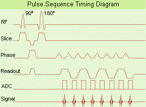
(FSE) In the pulse sequence timing diagram, a fast
spin echo sequence with an echo train length of 3 is
illustrated. This sequence is characterized by a series
of rapidly applied 180° rephasing pulses and multiple
echoes, changing the phase encoding gradient for each
echo.
The echo time TE may vary from echo to echo in the echo
train. The echoes in the center of the K-space (in the
case of linear k-space acquisition) mainly produce the
type of image contrast, whereas the periphery of K-space
determines the spatial resolution. For example, in the
middle of K-space the late echoes of T2 weighted images
are encoded. T1 or PD contrast is produced from the
early echoes.
The benefit of this technique is that the scan duration
with, e.g. a turbo spin echo turbo factor / echo train
length of 9, is one ninth of the time. In T1 weighted
and proton density weighted sequences, there is a limit
to how large the ETL can be (e.g. a usual ETL for T1
weighted images is between 3 and 7). The use of large
echo train lengths with short TE results in blurring and
loss of contrast. For this reason, T2 weighted imaging
profits most from this technique.
In T2 weighted FSE images, both water and fat are
hyperintense. This is because the succession of 180° RF
pulses reduces the spin spin interactions in fat and
increases its T2 decay time. Fast spin echo (FSE)
sequences have replaced conventional T2 weighted spin
echo sequences for most clinical applications. Fast spin
echo allows reduced acquisition times and enables T2
weighted breath hold imaging, e.g. for applications in
the upper abdomen.
In case of the acquisition of 2 echoes this type of a
sequence is named double fast spin echo / dual echo
sequence, the first echo is usually density and the
second echo is T2 weighted image. Fast spin echo images
are more T2 weighted, which makes it difficult to obtain
true proton density weighted images. For dual echo
imaging with density weighting, the TR should be kept
between 2000 - 2400 msec with a short ETL.
Other terms for this technique are:
Turbo Spin Echo
Rapid Imaging Spin Echo,
Rapid Spin Echo,
Rapid Acquisition Spin Echo,
Rapid Acquisition with Refocused Echoes
Advantages of TSE
With TSE, the scan time is decreased (due to faster
scanning) and the SNR is maintained because there are
still 256 phase-encoding steps. Motion artifacts will be
less severe and this technique is better able to cope
with poorly shimmed magnetic fields than conventional
spin echo. |
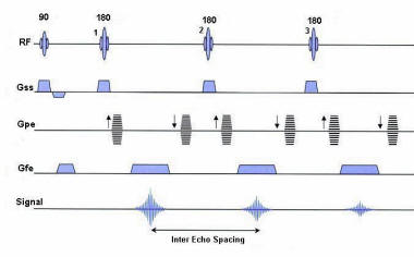 Turbo Spin Echo Sequence with three echoes
 |
|
Carr Purcell Sequence
(CPS) Sequence of a 90° RF pulse followed by repeated
180° RF pulses to produce a train of spin echoes; is
useful for measuring T2.
Carr Purcell Meiboom
Gill Sequence
(CPMG) This type of spin echo pulse sequence consisting
of a 90° radio frequency pulse followed by an echo train
induced by successive 180° pulses and is useful for
measuring T2 weighted images. It is a modification of
the Carr-Purcell RF pulse sequence, with 90° phase shift
in the rotating frame of reference between the 90° pulse
and the subsequent 180° pulses in order to reduce
accumulating effects of imperfections in the 180°
pulses. Suppression of effects of pulse error
accumulation can alternatively be achieved by switching
phases of the 180° pulses by 180°.
Double Fast Spin Echo
(DFSE) Simultaneously acquired T2 and density weighted
TE in FSE echo images.
Double Turbo Spin Echo
(DTSE / DE TSE) Simultaneously acquired T2 and density
weighted echoes in a TSE sequence.
Dual Echo Fast
Acquisition Interleaved Spin Echo
(DEFAISE) Simultaneously acquired T2 and density
weighted echoes in a FSE sequence.
Half Fourier
Acquisition Single Shot Turbo Spin Echo
(HASTE) A pulse sequence with data acquisition after an
initial preparation pulse for contrast enhancement with
the use of a very long echo train (Single shot TSE),
whereat each echo is individually phase encoded. This
technique is a heavily T2 weighted, high speed sequence
with partial Fourier technique, a great sensitivity for
fluid detection and a fast acquisition time of about 1
sec per slice. This advantage makes it possible for
using breath-hold with excellent motionless MRI, e.g.
used for liver and lung imaging.
See also Segmented HASTE.
Multiple Echo Single
Shot
(MESS) See Multiple Echo Imaging, Single Shot Technique
and Ultrafast Gradient Echo Sequence.
Rapid Acquisition with
Refocused Echoes
(RARE) If the image lines from multiple echoes are used
for the same image, this results in the RARE pulse
sequence. The sequence is similar to fast spin echo.
Turbo Spin Echo
(TSE) A pulse sequence characterized by a series of
rapidly applied 180° rephasing pulses and multiple
echoes.
Ultrashort Turbo Spin
Echo
(UTSE) The ultrashort turbo spin echo (TSE / FSE)
sequence is a technique with extremely short echo
spacing, resulting in shorter scan times. This is an
advantage in areas where motion is a problem, for
example dynamic or abdominal imaging. The shorter scan
time and echo spacing are achieved by using a higher TSE
factor and an increased data sampling rate.
Disadvantages are the decrease in SNR (caused through
the increase of the bandwidth) and artifacts if minimum
echo spacing is used (incomplete dephasing of the 180°
pulse FID). |
|
|
Inversion
Recovery Sequence |
|
|
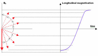
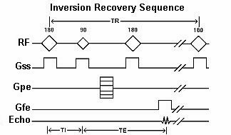
Inversion recovery is usually a variant of a SE sequence
in that it begins with a 180º inverting pulse. This
inverts the longitudinal magnetization vector through
180º. When the inverting pulse is removed, the
magnetization vector begins to relax back to B0. A 90º
excitation pulse is then applied after a time from the
180º inverting pulse known as the TI (time to
inversion). The contrast of the resultant image depends
primarily on the length of the TI as well as the TR and
TE. The contrast in the image primarily depends on the
magnitude of the longitudinal magnetization (as in spin
echo) following the chosen delay time TI. |
 |
|
(IR) The inversion recovery pulse sequence produces
signals, which represent the longitudinal magnetization
existing after the application of a 180° radio frequency
pulse that rotates the magnetization Mz into the
negative plane. After an inversion time (TI - time
between the starting 180° pulse and the following 90°
pulse), a further 90° RF pulse tilts some or all of the
z-magnetization into the xy-plane, where the signal is
usually rephased with a 180° pulse as in the spin echo
sequence. During the initial time period, various
tissues relax with their intrinsic T1 relaxation time.
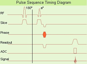
In the pulse sequence timing diagram, the basic
inversion recovery sequence is illustrated. The 180°
inversion pulse is attached prior to the 90° excitation
pulse of a spin echo acquisition. See also the Pulse
Sequence Timing Diagram. There you will find a
description of the components.
The inversion recovery sequence has the advantage, that
it can provide very strong contrast between tissues
having different T1 relaxation times or to suppress
tissues like fluid or fat. But the disadvantage is, that
the additional inversion radio frequency RF pulse makes
this sequence less time efficient than the other pulse
sequences.
Contrast values:
PD weighted: TE: 10-20 ms, TR: 2000 ms, TI: 1800 ms
T1 weighted: TE: 10-20 ms, TR: 2000 ms, TI: 400-800 ms
T2 weighted: TE: 70 ms, TR: 2000 ms, TI: 400-800 ms
See also Inversion Recovery, Short T1 Inversion
Recovery, Fluid Attenuation Inversion Recovery, and
Acronyms for 'Inversion Recovery Sequence' from
different manufacturers. Uses of
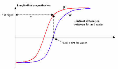
Inversion Recovery Sequence
Contrast is based on T1 recovery curves following the
180º inversion pulse. Inversion recovery is used to
produce heavily T1 weighted images to demonstrate
anatomy. The 180º inverting pulse can produce a large
contrast difference between fat and water because full
saturation of the fat or water vectors can be achieved
by utilizing the appropriate TI. |
 |
|
Flow Sensitive
Alternating Inversion Recovery
(FAIR) In this sequence 2 inversion recovery images are
acquired, one with a nonselective and the other with a
slice selective inversion pulse. The z-magnetization in
the first sequence is independent of flow. Inflowing
spins give z-magnetization from second pulse. A major
signal loss in FAIR is the T1 relaxation of tagged blood
in transit to the imaging slice. Sharper edges of the
inversion pulse give narrow spacing between the
inversion edge and the 1st slice because reduced transit
time gives lower T1 relaxation induced signal loss. The
difference of the images in a consequence contains
information proportional to flow (blood partition
coefficient). Standard adiabatic inversion RF pulse does
not have good slice-profile, because of power/SAR
limitation. A c-shaped frequency offset corrected
inversion (FOCI) RF pulse can help to increase the
signal.
Perfusion imaging, e.g. myocardial, using tissue water
as endogenous contrast is suggested.
|
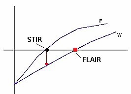
Fluid Attenuation
Inversion Recovery
(FLAIR) Fluid attenuation inversion recovery is a
special inversion recovery sequence with long TI to
remove the effects of fluid from the resulting images.
The TI time of the FLAIR pulse sequence is adjusted to
the relaxation time of the component that should be
suppressed. For fluid suppression the inversion time
(long TI) is set to the zero crossing point of fluid,
resulting in the signal being 'erased'.
Lesions that are normally covered by bright fluid
signals using conventional T2 contrast are made visible
by the dark fluid technique FLAIR is an important
technique for the differentiation of brain and spine
lesions.
Short T1 Inversion
Recovery
(STIR) Also called Short Tau (t) (inversion time)
Inversion Recovery. STIR is a fat suppression technique
with an inversion time TI = T1 ln2 where the signal of
fat is zero (T1 is the spin lattice relaxation time of
the component that should be suppressed). To distinguish
two tissue components with this technique, the T1 values
must be different. Fluid Attenuation Inversion Recovery
(FLAIR) is a similar technique to suppress water.
Inversion recovery doubles the distance spins will
recover, allowing more time for T1 differences. A 180°
preparation pulse inverts the net magnetization to the
negative longitudinal magnetization prior to the 90°
excitation pulse. This specialized application of the
inversion recovery sequence set the inversion time (TI)
of the sequence at 0.69 times the T1 of fat. The T1 of
fat at 1.5 Tesla is approximately 250 with a null point
of 170 ms while at 0.5 Tesla its 215 with a 148 ms null
point. At the moment of excitation, about 120 to 170 ms
after the 180° inversion pulse (depending of the
magnetic field) the magnetization of the fat signal has
just risen to zero from its original, negative, value
and no fat signal is available to be flipped into the
transverse plane.
When deciding on the optimal T1 time, factors to be
considered include not only the main field strength, but
also the tissue to be suppressed and the anatomy. In
comparison to a conventional spin echo where tissues
with a short T1 are bright due to faster recovery, fat
signal is reversed or darkened. Because body fluids have
both a long T1 and a long T2, it is evident that STIR
offers the possibility of extremely sensitive detection
of body fluid. This is of course, only true for
stationary fluid such as edema, as the MRI signal of
flowing fluids is governed by other factors. |
No Fat Vector when the 900 is applied |
| |
|
Inversion Recovery
Spin Echo
(IRSE) Form of inversion recovery imaging in which the
signal is detected as a spin echo. For TE short compared
to the T2 relaxation time, there will be only a small
effect of T2 differences on image intensities; for
longer TE's, the effect of T2 may be significant.
Turbo Inversion
Recovery
( TIR / TIRM / IR-TSE - Inversion Recovery Turbo Spin
Echo / FIR - Fast Inversion Recovery)
A turbo / fast spin echo sequence with long TI for fluid
suppression (FLAIR) or with short TI for fat suppression
(STIR). This sequence allows for a true inversion
recovery display that shows the arithmetic sign of the
signal.
TIRM means a turboIR with a magnitude display. |
|
|
Gradient Echo
Sequence |
|
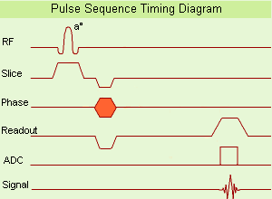
(GRE - sequence) A gradient echo is generated by
using a pair of bipolar gradient pulses. In the pulse
sequence timing diagram, the basic gradient echo
sequence is illustrated. There is no refocusing 180°
pulse and the data are sampled during a gradient echo,
which is achieved by dephasing the spins with a
negatively pulsed gradient before they are rephased by
an opposite gradient with opposite polarity to generate
the echo.
See also the Pulse Sequence Timing Diagram. There you
will find a description of the components.
The excitation pulse is termed the alpha pulse a. It
tilts the magnetization by a flip angle a, which is
typically between 0° and 90°. With a small flip angle
there is a reduction in the value of transverse
magnetization that will affect subsequent RF pulses. The
flip angle can also be slowly increased during data
acquisition (variable flip angle: tilt optimized
nonsaturation excitation). The data are not acquired in
a steady state, where z-magnetization recovery and
destruction by ad-pulses are balanced. However, the
z-magnetization is used up by tilting a little more of
the remaining z-magnetization into the xy-plane for each
acquired imaging line.
Gradient echo imaging is typically accomplished by
examining the FID, whereas the read gradient is turned
on for localization of the signal in the readout
direction. T2* is the characteristic decay time constant
associated with the FID. The contrast and signal
generated by a gradient echo depend on the size of the
longitudinal magnetization and the flip angle. When a =
90° the sequence is identical to the so-called partial
saturation or saturation recovery pulse sequence. In
standard GRE imaging, this basic pulse sequence is
repeated as many times as image lines have to be
acquired. Additional gradients or radio frequency pulses
are introduced with the aim to spoil to refocus the
xy-magnetization at the moment when the spin system is
subject to the next a pulse.
As a result of the short repetition time, the
z-magnetization cannot fully recover and after a few
initial a pulses there is an equilibrium established
between z-magnetization recovery and z-magnetization
reduction due to the a pulses.
Gradient echoes have a lower SAR, are more sensitive to
field inhomogeneities and have a reduced crosstalk, so
that a small or no slice gap can be used. In or out of
phase imaging depending on the selected TE (and field
strength of the magnet) is possible. As the flip angle
is decreased, T1 weighting can be maintained by reducing
the TR. T2* weighting can be minimized by keeping the TE
as short as possible, but pure T2 weighting is not
possible. By using a reduced flip angle, some of the
magnetization value remains longitudinal (less time
needed to achieve full recovery) and for a certain T1
and TR, there exist one flip angle that will give the
most signal, known as the "Ernst angle".
Contrast values:
PD weighted: Small flip angle (no T1), long TR (no T1)
and short TE (no T2*)
T1 weighted: Large flip angle (70°), short TR (less than
50ms) and short TE
T2* weighted: Small flip angle, some longer TR (100 ms)
and long TE (20 ms)
Classification of GRE sequences can be made into four
categories:
T1 weighted or incoherent/(RF or gradient) spoiled GRE
sequences ( FLASH)
T1/T2* weighted or coherent//refocused GRE sequences
T2 weighted contrast enhanced GRE sequences
ultrafast GRE sequences |
 |
|
 Flip Angle and Ernst Angle Flip Angle and Ernst Angle
In GE sequences, the choice of flip angle (α) is
important for achieving T1-weighted
images. GE sequences generally use small flip angles (<
90°) and very short TRs (typically
150 ms) The diagram shows that the optimal flip
angle depends on the T1 value of
the tissue being imaged. A short T1 results in a larger
optimal flip angle. The dotted line
represents the best contrast-to-noise ratio for marrow,
cartilage and bone for a TR of 100
ms.
For each value of T1, there is an
optimum flip angle that will give the most signal from a
sequence where repeated RF excitations are made. This is
known as the Ernst Angle and is given by:
αErnst = cos-1[exp(-TR/T1)]
|
Choice of Flip Angle Determines Optimum Tissue Contrast
2 |
|
|
Balanced
Sequence |
|
This family of sequences uses a
balanced gradient waveform. This waveform will act on
any stationary spin on resonance between 2 consecutive
RF pulses and return it to the same phase it had before
the gradients were applied. A balanced sequence starts
out with a RF pulse of 90° or less and the spins in the
steady state. Prior to the next TR in the slice
encoding, the phase encoding and the frequency encoding
direction, gradients are balanced so their net value is
zero. Now the spins are prepared to accept the next RF
pulse, and their corresponding signal can become part of
the new transverse magnetization. If the balanced
gradients maintain the longitudinal and transverse
magnetization, the result is that both T1 and T2
contrast are represented in the image.
This pulse sequence produces images with increased
signal from fluid (like T2 weighted sequences), along
with retaining T1 weighted tissue contrast. Balanced
sequences are particularly useful in cardiac MRI.
Because this form of sequence is extremely dependent on
field homogeneity, it is essential to run a shimming
prior the acquisition.
Usually the gray and white matter contrast is poor,
making this type of sequence unsuited for brain MRI.
Modifications like ramping up and down the flip angles
can increase signal to noise ratio and contrast of brain
tissues (suggested under the name COSMIC - Coherent
Oscillatory State acquisition for the Manipulation of
Image Contrast).
These sequences include e.g. Balanced Fast Field Echo
(bFFE), Balanced Turbo Field Echo (bTFE), Fast Imaging
with Steady Precession (TrueFISP, sometimes short
TRUFI), Completely Balanced Steady State (CBASS) and
Balanced SARGE (BASG).
Balanced Fast Field
Echo
(bFFE) A FFE sequence using a balanced gradient waveform. A
balanced sequence starts out with a RF pulse of 90° or less and
the spins in the steady state. Before the next TR in the slice
phase and frequency encoding, gradients are balanced so their
net value is zero. Now the spins are prepared to accept the next
RF pulse, and their corresponding signal can become part of the
new transverse magnetization. Since the balanced gradients
maintain the transverse and longitudinal magnetization, the
result is, that both T1 and T2 contrast are represented in the
image. This pulse sequence produces images with increased signal
from fluid, along with retaining T1 weighted tissue contrast.
Because this form of sequence is extremely dependent on field
homogeneity, it is essential to run a shimming prior the
acquisition. A fully balanced (refocused) sequence would yield
higher signal, especially for tissues with long T2 relaxation
times.
Balanced SARGE
(BASG) The spoiled steady state acquisition rewinded gradient
echo sequence with balanced waveform.
Balanced Turbo Field
Echo
(BTFE) A gradient echo pulse sequence with a balanced gradient
waveform and data acquisition after an initial preparation pulse
for contrast enhancement.
Fast Imaging with
Steady Precession - FISP - Rewound GE - GRASS
(TrueFISP) True fast imaging with steady state precession is a
coherent technique that uses a fully balanced gradient waveform.
The image contrast with TrueFISP is determined by T2*//T1
properties and mostly depending on TR. The speed and relative
motion insensitivity of acquisition help to make the technique
reliable, even in patients who have difficulty with holding
their breath.
Recent advances in gradient hardware have led to a decreased
minimum TR. This combined with improved field shimming
capabilities and signal to noise ratio, has allowed TrueFISP
imaging to become practical for whole-body applications. There's
mostly T2* weighting. With the used ultrashort TR-times T1
weighting is almost impossible. One such application is cardiac
cine MR with high myocardium-blood contrast. Spatial and
temporal resolution can be substantially improved with this
technique, but contrast on the basis of the ratio of T2* to T1
is not sufficiently high in soft tissues. By providing T1
contrast, TrueFISP could then document the enhancement effects
of T1 shortening contrast agents. These properties are useful
for the anatomical delineation of brain tumors and normal
structures. With an increase in SNR ratio with minimum TR,
TrueFISP could also depict the enhancement effect in myoma
uteri. True FSIP is a technique that is well suited for cardiac
MR imaging. The imaging time is shorter and the contrast between
the blood and myocardium is higher than that of FLASH.
|
|
Coherent
Gradient Echo |
|
Coherent gradient echo sequences can
measure the free induction decay (FID), generated just
after each excitation pulse or the echo formed prior to
the next pulse. Coherent gradient echo sequences are
very sensitive to magnetic field inhomogeneity. An
alternative to spoiling is to incorporate residual
transverse magnetization directly into the longitudinal
steady state. These GRE sequences use a refocusing
gradient in the phase encoding direction during the end
module to maximize remaining transverse (xy)
magnetization at the time when the next excitation is
due, while the other two gradients are, in any case,
balanced.
When the next excitation pulse is sent into the system
with an opposed phase, it tilts the magnetization in the
-a direction. As a result the z-magnetization is again
partly tilted into the xy-plane, while the remaining
xy-magnetization is tilted partly into the z-direction.
A fully refocused sequence with a properly selected and
uniform f would yield higher signal, especially for
tissues with long T2 relaxation times (high water
content) so it is used in angiographic, myelographic or
arthrographic examinations and is used for T2*
weighting. The repetition time for this sequence has to
be short. With short TR, coherent GE is also useable for
breath hold and 3D technique. If the repetition time is
about 200 msec there's no difference between spoiled or
unspoiled GE. T1 weighting is better with spoiled
techniques.
The common types include GRASS, FISP, FAST, and FFE.
The T2* component decreases with long TR and short TE.
The T1 time is controlled by flip angle. The common TR
is less than 50 ms and the common TE less than 15 ms
Other types have stronger T2 dependence but lower SNR.
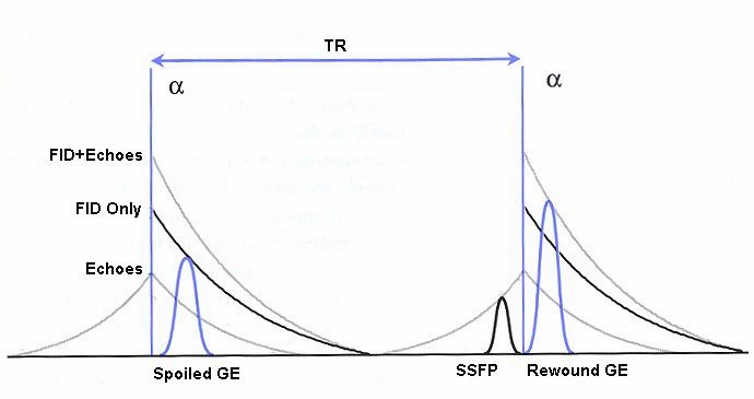
They include SSFP, CE-FAST, PSIF, and CE-FFE-T2.
Examples of fully refocused FID sequences are TrueFISP,
bFFE and bTFE.
Gradient Field Echo
with Contrast
(GFEC) A contrast enhanced gradient echo sequence.
Inversion Recovery
Fast Gradient Recalled Acquisition in the Steady State
(IR FGR) A gradient echo sequence with an inversion pulse.
Fast Field Echo
(FFE) An echo signal generated from a FID by means of a bipolar
switched magnetic gradient. The preparation module of the pulse
sequence consists of an excitation pulse. The magnetization
tilts by a flip angle between 0° and 90°.
Fast Imaging with
Steady State Precession
(FISP) A fast imaging sequence, which attempts to combine the
signals observed separately in the FADE sequence, generally
sensitive about magnetic susceptibility artifacts and
imperfections in the gradient waveforms. Confusingly now often
used to refer to a refocused FLASH type sequence.
This sequence is very similar to FLASH, except that the spoiler
pulse is eliminated. As a result, any transverse magnetization
still present at the time of the next RF pulse is incorporated
into the steady state. FISP uses a RF pulse that alternates in
sign. Because there is still some remaining transverse
magnetization at the time of the RF pulse, a RF pulse of a
degree flips the spins less than a degree from the longitudinal
axis. With small flip angles, very little longitudinal
magnetization is lost and the image contrast becomes almost
independent of T1. Using a very short TE (with TR 20-50 ms, flip
angle 30-45°) eliminates T2* effects, so that the images become
proton density weighted. As the flip angle is increased, the
contrast becomes increasingly dependent on T1 and T2*. It is in
the domain of large flip angles and short TR that FISP exhibits
vastly different contrast to FLASH type sequences. Used for T1
orthopedic imaging, 3D MPR, cardiography and angiography.
Fourier Acquired
Steady State
(FAST) A gradient echo sequence with steady state free
precession.
Reverse Fast Imaging
with Steady State Precession
(PSIF) A heavily T2* weighted contrast enhanced gradient echo
(mirrored FISP) technique. Because TE is relatively long, there
are much flow artifacts and less signal to noise. In normal
gradient echo techniques a FID-signal results after the RF
pulses. This FID is rephased very fast and just before the next
FID follows a spin echo signal. The SE is spoiled in FLASH
sequences, but with PSIF sequences, only the SE is measured, not
the FID.
SHORT Repetition
Technique Based on Free Induction Decay
(F-SHORT) A gradient echo sequence.
Steady State Free
Precession Sequence
(SFP or SSFP) Steady state free precession is any field or
gradient echo sequence where the TR is shorter than the T1 and
T2 times of the tissue.
The flip angle and the TR maintain the steady state. The flip
angle should be 60-90° if the TR is 100 ms, if the TR is less
than 100 ms, than the choice of the flip angle for steady state
is 45-60°. The T1 weighting is controlled by TR and flip, the T2
weighting increases with the TE. Common TR is between 20 - 50
msec.
|
|
Driven
Equilibrium |
|
In fast imaging sequences driven
equilibrium sensitizes the sequence to variations in T2.
This MRI technique turns transverse magnetization Mxy to
the longitudinal axis using a pulse rather than waiting
for T1 relaxation.
The first two pulses form a spin echo and, at the peak
of the echo, a second 90° pulse returns the
magnetization to the z-axis in preparation for a fresh
sequence. In the absence of T2 relaxation, then all the
magnetization can be returned to the z-axis. Otherwise,
T2 signal loss during the sequence will reduce the final
z-magnetization.
The advantage of this sequence type is, that both
longitudinal and also transverse magnetization are back
to equilibrium in a shorter amount of time. Therefore,
contrast and signal can be increased while using a
shorter TR. This pulse type can be applied to other
sequences like FSE, GE or IR.
Sequences with driven equilibrium:
Driven Equilibrium Fast Gradient Recalled acquisition in
the steady state - DE FGR,
Driven Equilibrium Fourier Transformation - DEFT,
Driven Equilibrium magnetization preparation - DE prep,
Driven Equilibrium Fast Spin Echo - DE FSE.
Driven Equilibrium
Fast Gradient Recalled Acquisition in the Steady State
(DE FGR) A gradient echo sequence using a pulse, which
sensitizes the sequence to variations in T2, rather than waiting
for T1 relaxation.
Driven Equilibrium
Fast Spin Echo
(DE FSE) A fast spin echo sequence with application of a pulse,
which sensitizes the sequence to variations in T2.
Driven Equilibrium
Fourier Transformation
(DEFT) This sequence enhances fluid signal by using a 'tip-up'
pulse following a spin echo train.
Driven Equilibrium
Magnetization Preparation
(DE prep)
|
|
Refocused
Gradient Echo Sequence |
|
Refocused GRE sequences use a
refocusing gradient in the phase encoding direction
during the end module to maximize (refocus) remaining
xy- (transverse) magnetization at the time when the next
excitation is due, while the other two gradients are, in
any case, balanced.
When the next excitation pulse is sent into the system
with an opposed phase, it tilts the magnetization in the
a direction. As a result the z-magnetization is again
partly tilted into the xy-plane, while the remaining
xy-magnetization is tilted partly into the z-direction.
Companies use different acronyms to describe certain
techniques.
Different terms for these gradient echo pulse sequences:
R-GRE Refocused Gradient Echo,
FAST Fourier Acquired Steady State,
FFE Fast Field echo,
FISP Fast Imaging with Steady State Precession,
F-SHORT SHORT Repetition Technique Based on Free
Induction Decay,
GFEC Gradient Field Echo with Contrast,
GRASS Gradient Recalled Acquisition in Steady State,
ROAST Resonant Offset Averaging in the Steady State,
SSFP Steady State Free Precession.
STERF Steady State Technique with Refocused FID
In this context, 'contrast' refers to the pulse
sequence, it does not mean enhancement with a contrast
agent.
Complex Rephasing Integrated with Surface Probes
(CRISP) A specific pulse sequence, wherein the application of
strategic gradient pulses can compensate for the objectionable
spin phase effects of flow motion.
Dual Fast Field Echo
(Dual/FFE) A FFE technique with simultaneously acquired in and
out of phase gradient echoes.
Dual Echo Fast Gradient Echo
(DE FGRE, Dual/FFE, DE FFE) Simultaneously acquired in and out
of phase TE gradient echo images. To quantitatively measure the
signal intensity differences between out of phase and in phase
images the parameters should be the same except for the TE.
The chemical shift artifact appearing on the out-of-phase image
allows for the detection of lipids in the liver or adrenal
gland, such as diffuse fatty infiltration, focal fatty
infiltration, focal fatty sparing, benign adrenocortical masses
and intracellular lipids within a hepatocellar neoplasm, where
spin echo and fat suppression techniques are not as sensitive.
Specific pathologies that have been reported include liver
lipoma, angiomyolipoma, myelolipoma, metastatic liposarcoma,
teratocarcinoma, melanoma, haemorrhagic neoplasm and metastatic
choriocarcinoma.
Fast Gradient Recalled Echo
(FGRE) The fast gradient recalled echo sequence belong to the
refocused gradient echo sequences.
Fast Field Echo
(FFE) An echo signal generated from a FID by means of a bipolar
switched magnetic gradient. The preparation module of the pulse
sequence consists of an excitation pulse. The magnetization
tilts by a flip angle between 0° and 90°.
Fast Imaging with Steady State Precession
(FISP) A fast imaging sequence, which attempts to combine the
signals observed separately in the FADE sequence, generally
sensitive about magnetic susceptibility artifacts and
imperfections in the gradient waveforms. Confusingly now often
used to refer to a refocused FLASH type sequence.
This sequence is very similar to FLASH, except that the spoiler
pulse is eliminated. As a result, any transverse magnetization
still present at the time of the next RF pulse is incorporated
into the steady state. FISP uses a RF pulse that alternates in
sign. Because there is still some remaining transverse
magnetization at the time of the RF pulse, a RF pulse of a
degree flips the spins less than a degree from the longitudinal
axis. With small flip angles, very little longitudinal
magnetization is lost and the image contrast becomes almost
independent of T1. Using a very short TE (with TR 20-50 ms, flip
angle 30-45°) eliminates T2* effects, so that the images become
proton density weighted. As the flip angle is increased, the
contrast becomes increasingly dependent on T1 and T2*. It is in
the domain of large flip angles and short TR that FISP exhibits
vastly different contrast to FLASH type sequences. Used for T1
orthopedic imaging, 3D MPR, cardiography and angiography.
Fast Low Angle Recalled Echoes
(FLARE) 'Fast Low Angle Recalled Echoes' is a gradient echo
sequence, typically with low flip angles and refocused gradient
echo.
Fourier Acquired Steady State
(FAST) A gradient echo sequence with steady state free
precession.
Gradient Field Echo with Contrast
(GFEC) A contrast enhanced gradient echo sequence.
Inversion Recovery Fast Gradient Recalled Acquisition in
the Steady State
(IR FGR) A gradient echo sequence with an inversion pulse.
Resonant Offset Averaging in the Steady State
(ROAST) A gradient echo sequence.
SHORT Repetition Technique Based on Free Induction Decay
(F-SHORT) A gradient echo sequence.
Steady State Free Precession Sequence
(SFP or SSFP) Steady state free precession is any field or
gradient echo sequence where the TR is shorter than the T1 and
T2 times of the tissue.
The flip angle and the TR maintain the steady state. The flip
angle should be 60-90° if the TR is 100 ms, if the TR is less
than 100 ms, than the choice of the flip angle for steady state
is 45-60°. The T1 weighting is controlled by TR and flip, the T2
weighting increases with the TE. Common TR is between 20 - 50
msec.
Steady State Technique with Refocused FID
(STERF) A gradient echo sequence
|
|
Spoiled
Gradient Echo Sequence - FLASH (
Fast Low Angle Shot ) |
|
Spoiled gradient echo sequences use a spoiler
gradient on the slice select axis during the end module
to destroy any remaining transverse magnetization after
the readout gradient, which is the case for short
repetition times.
As a result, only z-magnetization remains during a
subsequent excitation. This types of sequences use
semi-random changes in the phase of radio frequency
pulses to produce a spatially independent phase shift.
Companies use different acronyms to describe certain
techniques.
Different terms for these gradient echo pulse sequences:
CE-FFE-T1 Contrast Enhanced Fast Field Echo with T1
Weighting,
GFE Gradient Field Echo,
FLASH Fast Low Angle Shot,
PS Partial Saturation,
RF spoiled FAST RF Spoiled Fourier Acquired Steady State
Technique,
RSSARGE Radio Frequency Spoiled Steady State Acquisition
Rewound Gradient Echo
S-GRE Spoiled Gradient Echo,
SHORT Short Repetition Techniques,
SPGR Spoiled Gradient Recalled (spoiled GRASS),
STAGE T1W T1 weighted Small Tip Angle Gradient Echo,
T1-FAST T1 weighted Fourier Acquired Steady State
Technique,
T1-FFE T1 weighted Fast Field Echo.
Coherent and Incoherent Signal formation in the Steady
State resulting form a Rapid and Regular Train of RF
Pulses
The word “spoiling” refers to the elimination of the
steady-state transverse magnetization. There are various
ways of doing this, such as by applying RF spoiling,
applying variable gradient spoilers and by lengthening
TR. By eliminating the steady state component, only the
longitudinal component affects the signal in the FLASH
technique. This technique lends itself to reduced T2*
weighting and increased T1 weighting. This is true
provided that α is also large. When α is small, the T1
recovery curves play a minor role and proton density
(PD) weighting is increased.
|
|
Incoherent
Gradient Echo (Gradient spoiled) |
|
The incoherent gradient echo (gradient spoiled) type
of sequence uses a continuous shifting of the RF pulse
to spoil the remaining transverse magnetization. The
transverse magnetization is destroyed by a magnetic
field gradient. This results in a T1 weighted image.
Spoiling can be accomplished by RF or a gradient.
Gradient spoiling occurs after each echo by using strong
gradients in the slice-select direction after the
frequency encoding and before the next RF pulse. Because
spins in different locations in the magnet thereby
experience a variety of magnetic field strengths, they
will precess at differing frequencies; as a consequence
they will quickly become dephased. Magnetic field
gradients are not very efficient at spoiling the
transverse steady state. To be effective, the spins must
be forced to precess far enough to become phased
randomly with respect to the RF excitation pulse. In
clinical MRI machines, the field gradients are set up in
such a way that they increase and decrease relative to
the center of the magnet; the magnetic field at the
magnet 'isocenter' does not change.
The T1 weighting increases with the flip angle and the
T2* weighting increases with echo time (TE). Typical
repetition time (TR) are 30-500 ms and TE less than 15
ms.
Fast Low Angle Shot
(FLASH) A fast sequence producing signals called gradient echo
with low flip angles. FLASH sequences are modifications, which
incorporate or remove the effects of transverse coherence
respectively.
FLASH uses a semi-random spoiler gradient after each echo to
spoil the steady state (to destroy any remaining transverse
magnetization) by causing a spatially dependent phase shift. The
transverse steady state is spoiled but the longitudinal steady
state depends on the T1 values and the flip angle. Extremely
short TR times are possible, as a result the sequence provides a
mechanism for gaining extremely high T1 contrast by imaging with
TR times as brief as 20 to 30 msec while retaining reasonable
signal levels. It is important to keep the TE as short as
possible to suppress susceptibility artifacts.
The T1 contrast depends on the TR as well as on flip angle, with
short TE.
Small flip angles and short TR results in proton density, and
long TR in T2* weighting.
With large flip angles and short TR result T1 weighted images.
TR and flip angle adjustment:
TR 3000 ms, Flip Angle 90°
TR 1500 ms, Flip Angle 45°
TR 700 ms, Flip Angle 25°
TR 125 ms, Flip Angle 10°
The apparent ability to trade TR against flip angle for purposes
of contrast and the variation in SNR as the scan time (TR) is
reduced.
Multiplanar Gradient Recalled Acquisition in the Steady
State
(MPGR) Multiplanar gradient recalled acquisition in the steady
state is a term for a fast gradient echo sequence with slice
selective RF pulses.
Short Repetition Techniques
(SHORT) Gradient echo sequences.
Small Tip Angle Gradient Echo
(STAGE) A gradient echo sequence with low flip angles and
spoiled gradients.
|
|
Incoherent
Gradient Echo (RF spoiled) |
|
A gradient echo is generated by using a pair of
bipolar gradient pulses. The gradient field is
negatively pulsed, causing the spins of the
xy-magnetization to dephase. A second gradient pulse is
applied with the opposite polarity. During the pulsing,
the spins that dephased begin to rephase and generate a
gradient echo.
Spoiling can be accomplished by RF or a gradient. The
incoherent RF spoiled type of a gradient echo sequence
use a continuous shifting of the RF pulse to spoil the
residual transverse magnetization. The phase of the RF
excitation and receiver channel are varied pseudo
randomly with each excitation cycle to prevent the xy
magnetization from achieving steady state. T2* does not
dominate image contrast, so T1 and PD weighting is
practical. This method is effective and can be used to
achieve a shorter TR, due to a lack of additional
gradients. Spoiling eliminates the effect of the
remaining xy-magnetization and leads to steady state
longitudinal magnetization. These sequences can be used
for breath hold, dynamic imaging and in cine and volume
acquisitions.
Gradient Field Echo
Radio Frequency Spoiled Steady State Acquisition Rewound
Gradient Echo
(RSSARGE) A sequence with spoiled gradient echoes.
RF Spoiled Fourier Acquired Steady State Technique
(RF-FAST / RF spoiled FAST) A gradient echo sequence.
Small Tip Angle Gradient Echo T1 Weighted
(STAGE T1W) A RF spoiled T1 weighted gradient echo sequence.
Spoiled Gradient Recalled
(SPGR) The SPGR pulse sequence is similar to the spoiled GRASS
sequence. The spoiled gradient recalled (SPGR) acquisition in
steady state uses semi-random changes in the phase of the radio
frequency (RF) pulses to produce a spatially independent phase
shift.
|
|
Steady State
Free Precession - SSFP - PSIF |
|
( PSIF SFP or SSFP) Steady state free precession is any
field or gradient echo sequence in which a non-zero
steady state develops for both components of
magnetization (transverse and longitudinal) and also a
condition where the TR is shorter than the T1 and T2
times of the tissue. If the RF pulses are close enough
together, the MR signal will never completely decay,
implying that the spins in the transverse plane never
completely dephase. The flip angle and the TR maintain
the steady state. The flip angle should be 60-90° if the
TR is 100 ms, if the TR is less than 100 ms, then the
flip angle for steady state should be 45-60°.
Steady state free precession is also a method of MR
excitation in which strings of RF pulses are applied
rapidly and repeatedly with interpulse intervals short
compared to both T1 and T2. Alternating the phases of
the RF pulses by 180° can be useful. The signal reforms
as an echo immediately before each RF pulse;;
immediately after the RF pulse there is additional
signal from the FID produced by the pulse.
The strength of the FID will depend on the time between
pulses (TR), the tissue and the flip angle of the pulse;
the strength of the echo will additionally depend on the
T2 of the tissue. With the use of appropriate dephasing
gradients, the signal can be observed as a
frequency-encoded gradient echo either shortly before
the RF pulse or after it; the signal immediately before
the RF pulse will be more highly T2 weighted. The signal
immediately after the RF pulse (in a rapid series of RF
pulses) will depend on T2 as well as T1, unless measures
are taken to destroy signal refocusing and prevent the
development of steady state free precession.
To avoid setting up a state of SSFP when using rapidly
repeated excitation RF pulses, it may be necessary to
spoil the phase coherence between excitations, e.g. with
varying phase shifts or timing of the exciting RF pulses
or varying spoiler gradient pulses between the
excitations.
Steady state free precession imaging methods are quite
sensitive to the resonant frequency of the material.
Fluctuating equilibrium MR (see also FIESTA and
DRIVE) and linear combination SSFP actually use this
sensitivity for fat suppression. Fat saturated SSFP
(FS-SSFP) use a more complex fat suppression scheme than
FEMR or LCSSFP, but has a 40% lower scan time.
A new family of steady state free precession sequences
use a balanced gradient, a gradient waveform, which will
act on any stationary spin on resonance between 2
consecutive RF pulses and return it to the same phase it
had before the gradients were applied.
This sequences include, e.g. Balanced Fast Field Echo -
bFFE, Balanced Turbo Field Echo - bTFE, Fast Imaging
with Steady Precession - TrueFISP and Balanced SARGE -
BASG. See also FIESTA
Completely Balanced Steady State
(CBASS) A gradient echo sequence with balanced waveform.
Contrast Enhanced FAST
(CE-FAST) In this technique, the MR signal is sampled
immediately prior to each RF pulse. Because the signal is formed
by a true spin echo, its contrast is predominantly T2-, rather
than T2*-based and is less sensitive to artifacts and signal
losses related to field non-uniformity and susceptibility
variation. While the signal to noise ratio is limited, the
CE-FAST method has the advantage of good contrast.
Contrast Enhanced Fast Field Echo with T2 Star Weighting
(CE-FFE-T2) A T2* weighted gradient echo sequence.
Fast Imaging with Steady Precession
(TrueFISP) True fast imaging with steady state precession is a
coherent technique that uses a fully balanced gradient waveform.
The image contrast with TrueFISP is determined by T2*//T1
properties and mostly depending on TR. The speed and relative
motion insensitivity of acquisition help to make the technique
reliable, even in patients who have difficulty with holding
their breath.
Recent advances in gradient hardware have led to a decreased
minimum TR. This combined with improved field shimming
capabilities and signal to noise ratio, has allowed TrueFISP
imaging to become practical for whole-body applications. There's
mostly T2* weighting. With the used ultrashort TR-times T1
weighting is almost impossible. One such application is cardiac
cine MR with high myocardium-blood contrast. Spatial and
temporal resolution can be substantially improved with this
technique, but contrast on the basis of the ratio of T2* to T1
is not sufficiently high in soft tissues. By providing T1
contrast, TrueFISP could then document the enhancement effects
of T1 shortening contrast agents. These properties are useful
for the anatomical delineation of brain tumors and normal
structures. With an increase in SNR ratio with minimum TR,
TrueFISP could also depict the enhancement effect in myoma
uteri. True FSIP is a technique that is well suited for cardiac
MR imaging. The imaging time is shorter and the contrast between
the blood and myocardium is higher than that of FLASH.
Fourier Acquired Steady State
(FAST) A gradient echo sequence with steady state free
precession.
Driven Equilibrium Fast Gradient Recalled Acquisition in
the Steady State
(DE FGR) A gradient echo sequence using a pulse, which
sensitizes the sequence to variations in T2, rather than waiting
for T1 relaxation.
Reverse Fast Imaging with Steady State Precession
(PSIF) A heavily T2* weighted contrast enhanced gradient echo
(mirrored FISP) technique. Because TE is relatively long, there
are much flow artifacts and less signal to noise. In normal
gradient echo techniques a FID-signal results after the RF
pulses. This FID is rephased very fast and just before the next
FID follows a spin echo signal. The SE is spoiled in FLASH
sequences, but with PSIF sequences, only the SE is measured, not
the FID.
Steady State Gradient Echo with Spin Echo Sampling
(E-SHORT) A gradient echo sequence in which a non-zero steady
state develops for transverse and longitudinal magnetization.
The TR is shorter than the T1 and T2 times of the tissue.
Steady State Technique with Refocused FID
(STERF) A gradient echo sequence.
|
|
Ultrafast
Gradient Echo Sequence |
|
|
In simple ultrafast GRE imaging, TR and TE are so
short, that tissues have a poor imaging signal and —
more importantly — poor contrast except when contrast
media enhanced (contrast enhanced angiography).
Therefore, the magnetization is 'prepared' during the
preparation module, most frequently by an initial 180°
inversion pulse.
In the pulse sequence timing diagram, the basic
ultrafast gradient echo sequence is illustrated. The
180° inversion pulse is executed one time (to the left
of the vertical line), the right side represents the
data collection period and is often repeated depending
on the acquisition parameters.
See also Pulse Sequence Timing Diagram, there you will
find a description of the components.
Ultrafast GRE sequences have a short TR,TE, a low flip
angle and TR is so short that image acquisition lasts
less than 1 second and typically less than 500 ms.
Common TR: 3-5 msec, TE: 2 msec, and the flip angle is
about 5°. Such sequences are often labeled with the
prefix 'Turbo' like TurboFLASH, TurboFFE and TurboGRASS.
This allows one to center the subsequent ultrafast GRE
data acquisition around the inversion time TI, where one
of the tissues of interest has very little signal as its
z-magnetization is passing through zero.
Unlike a standard inversion recovery (IR) sequence, all
lines or a substantial segment of k-space image lines
are acquired after a single inversion pulse, which can
then together be considered as readout module. The
readout module may use a variable flip angle approach,
or the data acquisition may be divided into multiple
segments (shots). The latter is useful particularly in
cardiac imaging where acquiring all lines in a single
segment may take too long relative to the cardiac cycle
to provide adequate temporal resolution.
If multiple lines are acquired after a single pulse, the
pulse sequence is a type of gradient echo echo planar
imaging (EPI) pulse sequence.
|
 |
| |
|
|
Echo Planar Imaging
(EPI).
(EPI) Echo planar imaging is one of the early magnetic
resonance imaging sequences (also known as Intascan),
used in applications like diffusion, perfusion, and
functional magnetic resonance imaging. Other sequences
acquire one k-space line at each phase encoding step.
When the echo planar imaging acquisition strategy is
used, the complete image is formed from a single data
sample (all k-space lines are measured in one repetition
time) of a gradient echo or spin echo sequence (see
single shot technique) with an acquisition time of about
20 to 100 ms. The pulse sequence timing diagram
illustrates an echo planar imaging sequence from spin
echo type with eight echo train pulses. (See also Pulse
Sequence Timing Diagram, for a description of the
components.)
In case of a gradient echo based EPI sequence the
initial part is very similar to a standard gradient echo
sequence. By periodically fast reversing the readout or
frequency encoding gradient, a train of echoes is
generated.
EPI requires higher performance from the MRI scanner
like much larger gradient amplitudes. The scan time is
dependent on the spatial resolution required, the
strength of the applied gradient fields and the time the
machine needs to ramp the gradients.
In EPI, there is water fat shift in the phase encoding
direction due to phase accumulations. To minimize water
fat shift (WFS) in the phase direction fat suppression
and a wide bandwidth (BW) are selected. On a typical EPI
sequence, there is virtually no time at all for the flat
top of the gradient waveform. The problem is solved by
"ramp sampling" through most of the rise and fall time
to improve image resolution.
The benefits of the fast imaging time are not without
cost. EPI is relatively demanding on the scanner
hardware, in particular on gradient strengths, gradient
switching times, and receiver bandwidth. In addition,
EPI is extremely sensitive to image artifacts and
distortions. For More information about EPI click
here! |
 |
|
  |
Fast Spoiled Gradient Echo
(FSPGR) A sequence similar to TurboFLASH or Turbo Field
Echo.
Fourier Acquired Steady State
(FAST) A gradient echo sequence with steady state free
precession.
Gradient and Spin Echo
(GRASE) A hybrid sequence with a combination of gradient
and spin echo sequences. If multiple image lines are
obtained during a single echo, the imaging pulse
sequence type is a GRASE sequence.
Magnetization Prepared Rapid Gradient Echo
(MP-GRE / MPRAGE / MP-RAGE) A fast 3D gradient echo
pulse sequence using a magnetization preparation pulse
like TurboFLASH. Only one segment or partition of a 3D
data record is obtained per inversion preparation pulse.
After the acquisition, for all rows a delay time (TD) is
used to prevent saturation effects.
MPRAGE is designed for rapid acquisition with T1
weighted dominance. Fast gradient echoes are
characterized by their rapid sampling time, high signal
intensity and image contrast while approaching steady
state (the echo is collected during the time when
tissues are experiencing T1 relaxation). The rapid speed
of the acquisition makes it an excellent alternative to
breath-hold abdominal imaging, neuro, dynamic bolus, MR
angiography and cardiac imaging.
Rapid Acquisition Matrix FAST
(RAM-FAST) A fast gradient echo pulse sequence using a
magnetization preparation pulse
Rapid Scan
(RS) A very fast gradient echo sequence.
Short Minimum Angled Shot
(SMASH) A very fast gradient echo sequence.
Turbo Field Echo
(TFE) Turbo field echo is a gradient echo pulse sequence
with data acquisition after an initial 180° (similar to
IR) preparation pulse for contrast enhancement. The
difference between a FFE and TFE other than the speed of
the sequence is that the image is acquired while
approaching steady state (the echoes are collected
during the time in which the tissues are experiencing T1
relaxation).
The contrast is prepared one time, which means the
contrast is changing while the echoes are collected and
can be manipulated by selecting the type and timing of
the prepulse. A delay time is given before the actual
image acquistion. To achieve T1 contrast the 180°
prepulse is followed by an operator selected delay time,
that results in no signal from the targeted tissue. So
when the echoes are acquired, no signal is present,
additional RF spoiling is performed to optimize for T1
contrast. The delay chosen corresponds to when T1
relaxation reaches and suppresses T1 signal or optimizes
the difference between tissues. Contrast for these
sequences are enhanced when K-space is filled using a
centric or low-high ordering. A TFE can be acquired with
a 2D or 3D technique and with or without T1, T2
weighting.
Turbo Gradient Spin Echo
(TGSE / TurboGSE) A sequence with a combination of
Gradient and Spin Echo Imaging. Additional gradient
echoes are generated before and after each spin echo.
The spin echoes are allocated to the center of the raw
data matrix to give pure T2 contrast. The gradient
echoes primarily determine the image resolution. If
multiple image lines are obtained during a single echo,
the imaging pulse sequence type is a TGSE pulse
sequence. This sequence is very fast, fat is darker and
more sensitive to susceptibility effects. Also called
GRASE.
Turbo Gradient Recalled Acquisition in Steady State
(TurboGRASS) This GRASS-based sequence use an inversion
pulse followed by a low flip angle and short TR gradient
echo train.
Turbo Fast Low Angle Shot
(TurboFLASH) This FLASH-based sequence use an inversion
pulse followed by a low flip angle and short TR gradient
echo train. This gradient echo technique forms complete
images in times short compared to T1. Images obtained in
this way have very little intrinsic contrast,
maintaining adequate signal requires that losses (and
therefore contrast)
Volumetric Interpolated Breath Hold Examination
(VIBE) A T1 weighted 3D FLASH breath hold technique with
fat selective prepulse.
Used for dynamic liver, pancreas, pelvis, thorax, orbita
imaging and MR colonoscopy.
|
|
MR Angiography |
|
(MRA) Magnetic resonance angiography is a medical
imaging technique to visualize blood filled structures,
including arteries, veins and the heart chambers. This
MRI technique creates soft tissue contrast between blood
vessels and surrounding tissues primarily created by
flow, rather than displaying the vessel lumen. There are
bright blood and black blood MRA techniques, named
according to the appearance of the blood vessels. With
this different MRA techniques both, the blood flow and
the condition of the blood vessel walls can be seen.
Flow effects in MRI can produce a range of artifacts.
MRA takes advantage of these artifacts to create
predictable image contrast due to the nature of flow.
Technical parameters of the MRA sequence greatly affect
the sensitivity of the images to flow with different
velocities or directions, turbulent flow and vessel
size.
This are the three main types of MRA:
time of flight angiography (TOF)
phase contrast angiography (PCA)
contrast enhanced magnetic resonance angiography
(CE-MRA)
All angiographic techniques differentially enhance
vascular MR signal. The names of the bright blood
techniques TOF and PCA reflect the physical properties
of flowing blood that were exploited to make the vessels
appear bright. Contrast enhanced magnetic resonance
angiography creates the angiographic effect by using an
intravenously administered MR contrast agent to
selectively shorten the T1 of blood and thereby cause
the vessels to appear bright on T1 weighted images.
MRA images optimally display areas of constant blood
flow-velocity, but there are many situations where the
flow within a voxel has non-uniform speed or direction.
In a diseased vessel these patterns are even more
complex. Similar loss of streamline flow occurs at all
vessel junctions and stenoses, and in regions of mural
thrombosis. It results in a loss of signal, due to the
loss of phase coherence between spins in the voxel.
This signal loss, usually only noticeable distal to a
stenosis, used to be an obvious characteristic of MRA
images. It is minimized by using small voxels and the
shortest possible TE. Signal loss from disorganized flow
is most noticeable in TOF imaging but also affects the
PCA images.
Indications to perform a magnetic resonance angiography
(MRA):
Detection of aneurysms and dissections
Evaluation of the vessel anatomy, including variants
Blockage by a blood clot or stenosis of the blood vessel
caused by plaques (the buildup of fat and calcium
deposits)
Conventional angiography or computerized tomography
angiography (CT angiography) may be needed after MRA if
a problem (such as an aneurysm) is present or if surgery
is being considered.
Black Blood MRA
With this magnetic resonance angiography technique
flowing blood appears dark.
MR black blood techniques have been developed for
cardiovascular imaging to improve segmentation of
myocardium from the blood pool. Black blood MRA
techniques decrease the signal from blood with reference
to the myocardium and make it easier to perform cardiac
chamber segmentation.
ECG gated spin echo sequences with presaturation pulses
for magnetization preparation will show strong
intravascular signal loss due to flow effects when
appropriate imaging conditions including spatial
presaturation are used. The sequence use the flow void
effect as blood passes rapidly through the selected
slice.
For dark blood preparation, a pair of nonselective and
selective 180° inversion pulses are used, followed by a
long inversion time to null signal from inflowing blood.
A second selective inversion pulse can also be applied
with short inversion time to null the fat signal. These
in cardiac imaging used black blood techniques are
referred to as double inversion recovery T1 measurement
turbo spin echo or fast spin echo, and double-inversion
recovery STIR.
Contrast Enhanced Magnetic Resonance Angiography
(CE MRA) Contrast enhanced MR angiography is based on
the T1 values of blood, the surrounding tissue, and
paramagnetic contrast agent.
T1-shortening contrast agents reduces the T1 value of
the blood (approximately to 50 msec, shorter than that
of the surrounding tissues) and allow the visualization
of blood vessels, as the images are no longer dependent
primarily on the inflow effect of the blood. Contrast
enhanced MRA is performed with a short TR to have low
signal (due to the longer T1) from the stationary
tissue, short scan time to facilitate breath hold
imaging, short TE to minimize T2* effects and a bolus
injection of a suffizient dose of a gadolinium chelate.
Images of the region of interest are performed with 3D
spoiled gradient echo pulse sequences. The enhancement
is maximized by timing the contrast agent injection such
that the period of maximum arterial concentration
corresponds to the k-space acquisition. Different
techniques are used to ensure optimal contrast of the
arteries e.g., bolus timing, automatic bolus detection,
bolus tracking, care bolus. A high resolution with near
isotropic voxels and minimal pulsatility and
misregistration artifacts should be striven for. The
postprocessing with the maximum intensity projection
(MIP) enables different views of the 3D data set.
Unlike conventional MRA techniques based on velocity
dependent inflow or phase shift techniques, contrast
enhanced MRA exploits the gadolinium induced
T1-shortening effects. CE MRA reduces or eliminates most
of the artifacts of time of flight angiography or phase
contrast angiography. Advantages are the possibility of
inplane imaging of the blood vessels, which allows to
examine large parts in a short time and high resolution
scans in one breath hold. CE MRA has found a wide
acceptance in the clinical routine, caused by the
advantages:
3D MRA can be acquired in any plane, which means that
greater vessel coverage can be obtained at high
resolution with fewer slices (aorta, peripheral
vessels);
the possibility to perform a time resolved examination
(similarly to conventional angiography);
no use of ionizing radiation; paramagnetic agents have a
beneficial safety.
Phase Contrast Angiography
(PCA) With this method images of the blood flow-velocity
(or any other movement of tissue) are produced. The MRI
signal contains both amplitude and phase information.
The phase information can be used with subtraction of
images with and without a velocity encoding gradient.
The signal will be directly proportional to the velocity
because of the relation between blood flow-velocity and
signal intensity.
This is the strength of PCA, complete suppression of
stationary tissue (no velocity - no signal), the direct
velocity of flow is being imaged, while in TOF (Inflow)
angiography, tissue with short T1 (fat or methaemoglobin)
might be visualized.
The strength of the gradient determines the sensitivity
to flow. It is set by setting the aliasing or encoding
velocity (VENC). Unfortunately, phase sensitization can
only be acquired along one axis at a time. Therefore,
phase contrast angiographic techniques tend to be 4
times slower than TOF techniques with the same matrix.
Time of Flight Angiography
(TOF) The time of flight angiography is used for the
imaging of vessels. Usually the sequence type is a
gradient echo sequences with short TR, acquired with
slices perpendicular to the direction of blood flow.
The source of diverse flow effects is the difference
between the unsaturated and presaturated spins and
creates a bright vascular image without the invasive use
of contrast media. Flowing blood moves unsaturated spins
from outside the slice into the imaging plane. These
completely relaxed spins have full equilibrium
magnetization and produce (when entering the imaging
plane) a much higher signal than stationary spins if a
gradient echo sequence is generated. This flow related
enhancement is also referred to as entry slice
phenomenon, or inflow enhancement.
Performing a presaturation slab on one side parallel to
the slice can selectively destroy the MR signal from the
in-flowing blood from this side of the slice. This
allows the technique to be flow direction sensitive and
to separate arteriograms or venograms. When the local
magnetization of moving blood is selectively altered in
a region, e.g. by selective excitation, it carries the
altered magnetization with it when it moves, thus
tagging the selected region for times on the order of
the relaxation times.
For maximum flow signal, a complete new part of blood
has to enter the slice every repetition (TR) period,
which makes time of flight angiography sensitive to
flow-velocity. The choice of TR and slice thickness
should be appropriate to the expected flow-velocities
because even small changes in slice thickness influences
the performance of the TOF sequence. The use of
sequential 2 dimensional Fourier transformation (2DFT)
slices, 3DFT slabs, or multiple 3D slabs (chunks) are
depending on the coverage required and the range of
flow-velocities.
3D TOF MRA is routinely used for evaluating the Circle
of Willis.
| Sequences in Aera |
| |
Matrix |
| 64 |
128 |
256 |
| Spin
Echo |
min. TR [ms] |
6.8 |
7.2 |
7.8 |
| min. TE [ms] |
3 |
3.5 |
4 |
|
Inversion Recovery |
min. TR [ms] |
28 |
29 |
30 |
| min. TE [ms] |
3 |
3.5 |
4 |
| min. TI [ms] |
23 |
23 |
23 |
| 2D GRE |
min. TR [ms] |
0.68 |
0.92 |
1.14 |
| min. TE [ms] |
0.28 |
0.28 |
0.28 |
| 3D GRE |
min. TR [ms] |
0.68 |
0.92 |
1.14 |
| min. TE [ms] |
0.28 |
0.28 |
0.28 |
|
TrueFISP |
min. TR [ms] |
1.9 |
2.1 |
2.76 |
| min. TE [ms] |
0.88 |
0.89 |
1.16 |
| TSE
(HASTE) |
min. Echo Spacing
[ms] |
2.08 |
2.38 |
2.9 |
| min. TR [ms] |
6.8 |
7.2 |
7.8 |
| min. TE [ms] |
3 |
3.5 |
4 |
| max.
Turbo Factor = 512 |
| Turbo
GSE |
min. Echo Spacing
[ms] |
0.8 |
0.96 |
1.16 |
| min. TR [ms] |
6.8 |
7.2 |
7.8 |
| min. TE [ms] |
3 |
3.5 |
4 |
| max. Turbo Factor |
65 |
65 |
65 |
| max.
EPI Factor = 21 |
| EPI
(single-shot and multi-shot) |
min. Echo Spacing
[ms] |
0.38 |
0.55 |
0.9 |
| min. TR [ms] |
10 |
10 |
10 |
| min. TE [ms] |
2.1 |
2.4 |
2.9 |
| min. Measurement
time |
15 |
19 |
30 |
| max.
EPI Factor = 256 |
|
Diffusion Imaging |
Max. b-value [s /
mm2] |
10 000 |
10 000 |
10 000 |
| Min. TE [ms] with
b = 1000 [s / mm2] |
49 |
51 |
56 |
| All matrices
without interpolation. Combinations of the stated
parameters are not always possible; |
| some parameters may
require optional application packages. These data are
applicable for Aera |
|
| Sequences in Skyra |
| |
Matrix |
| 64 |
128 |
256 |
| Spin
Echo |
min. TR [ms] |
5.7 |
6.3 |
6.4 |
| min. TE [ms] |
3 |
3.3 |
3.5 |
|
Inversion Recovery |
min. TR [ms] |
27 |
28 |
28 |
| min. TE [ms] |
3 |
3.3 |
3.5 |
| min. TI [ms] |
22 |
22 |
22 |
| 2D GRE |
min. TR [ms] |
0.54 |
0.67 |
1 |
| min. TE [ms] |
0.22 |
0.22 |
0.22 |
| 3D GRE |
min. TR [ms] |
0.54 |
0.67 |
1 |
| min. TE [ms] |
0.22 |
0.22 |
0.22 |
|
TrueFISP |
min. TR [ms] |
2.03 |
2.22 |
2.7 |
| min. TE [ms] |
0.94 |
0.98 |
1.19 |
| TSE
(HASTE) |
min. Echo Spacing
[ms] |
1.92 |
2.12 |
2.5 |
| min. TR [ms] |
5.7 |
6.3 |
6.4 |
| min. TE [ms] |
3 |
3.3 |
3.5 |
| max.
Turbo Factor = 512 |
| Turbo
GSE |
min. Echo Spacing
[ms] |
0.7 |
0.82 |
0.86 |
| min. TR [ms] |
5.7 |
6.3 |
6.4 |
| min. TE [ms] |
3 |
3.5 |
3.5 |
| max. Turbo Factor |
65 |
65 |
65 |
| max.
EPI Factor = 21 |
| EPI
(single-shot and multi-shot) |
min. Echo Spacing
[ms] |
0.28 |
0.4 |
0.66 |
| min. TR [ms] |
10 |
10 |
10 |
| min. TE [ms] |
2.1 |
2.2 |
2.7 |
| min. Measurement
time |
12 |
17 |
25 |
| max.
EPI Factor = 256 |
|
Diffusion Imaging |
Max. b-value [s /
mm2] |
10 000 |
10 000 |
10 000 |
| Min. TE [ms] with
b = 1000 [s / mm2] |
42 |
43 |
47 |
| All matrices
without interpolation. Combinations of the stated
parameters are not always possible; |
| some parameters may
require optional application packages. These data are
applicable for Skyra |
|
| |
|
|
|
|